
0x00 前言
RP2040 为 C/C++ 和 Python 编程提供了官方支持,我们可以在 RP2040 上运行主线 MicroPython。文档中称:
For exceptionally demanding pieces of software, you can fall back on the SDK (covered in Getting started with Raspberry Pi Pico and Raspberry Pi Pico C/C++ SDK), or an external C module added to your MicroPython firmware, to wring out the very last drop of performance. For every other project, MicroPython handles a lot of heavy lifting for you, and lets you focus on writing the code that adds value to your project.
随着计算资源的提升,编程的发展趋势必定是由硬变软的,在降低程序员的心智负担的同时,让更多的平凡人能轻松实现自己的需求。我们曾经从机器码过渡到汇编、从汇编过渡到 C 语言,未来也必将从 C 语言过渡到更简单的语言。目前来看,python 和 lua 都有成为嵌入式编程主流语言的潜力。本文将讨论 MicroPython 在 RP2040 上的使用。我们的最终目标是:利用较少的代码量,实现一个联网的温湿度计,每 10s 从 DHT11 传感器采集温湿度信息,将数据显示在 OLED 屏幕上,并通过 WiFi 报告给服务器。
在动手操作之前,我们不妨先做个思维游戏:如果我们自己要把 python/lua 移植到 MCU 上,需要付出哪些努力呢?首先,从硬件资源上讲,运行一个完整的主线 lua 或许可行,但主线 python 不太可能跑得起来,我们需要裁剪掉一些功能。其次,MCU 上没有操作系统,无法发起 syscall,所以 fork() 之类的 API 要删掉,read() 之类的 API 需要重写,依赖于文件系统的功能(例如 import)要么丢弃,要么先在 flash 上实现文件系统,再集成到程序中。另外,MCU 上没有 MMU,我们得放弃 mmap 之类的 API,改为手动管理硬件内存。最后,我们需要一个轻量级 gc,以便在不太影响实时性的前提下,管理宝贵的内存资源。综合以上种种考虑,我们对 lua 应该移植,对 python 可能直接重写比较合适。
现在,我们先试试在 Pico W 开发板上运行预编译的 MicroPython 固件。
0x01 烧录固件和初次运行
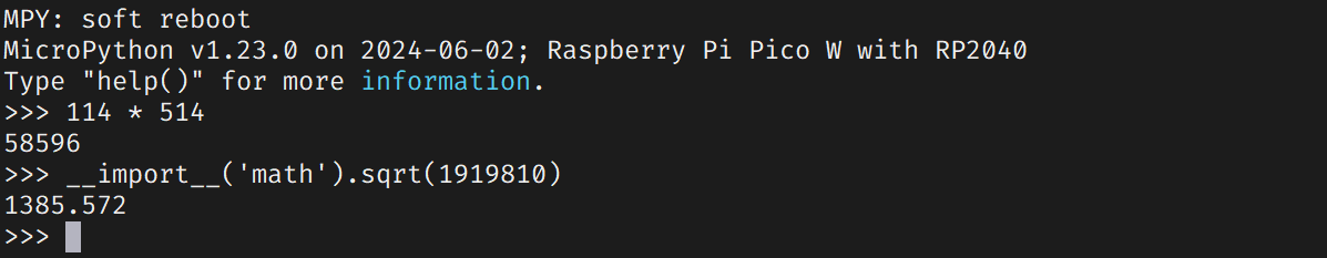
从 MicroPython 官网上下载 uf2 格式的 Pico W 固件(大约 1.6MB),按住 BOOTSEL 上电,把 uf2 文件拖进虚拟 u 盘中。烧录完成之后,RP2040 会重启,此时可以通过 usb 串口连接 REPL。
ports/rp2/mpconfigport.h 以将 REPL 暴露给 uart0。按 Ctrl+D 软重启:
点亮 LED:
from machine import Pin
led = Pin("LED", Pin.OUT)

led.value(1)
led.value(0)
上一篇文章提到过,Pico W 想要点亮 LED,需要通过 spi 协议发消息给无线芯片;但神奇的是,上述代码与常规的 GPIO 控制没有区别。我们深入源码,看看这是怎么实现的。先 clone 项目:
git clone https://github.com/micropython/micropython.git --branch master --depth=1在 ports/rp2/boards/RPI_PICO_W/pins.csv 中,有这样几行:
......
GP26,GPIO26
GP27,GPIO27
GP28,GPIO28
WL_GPIO0,EXT_GPIO0
WL_GPIO1,EXT_GPIO1
WL_GPIO2,EXT_GPIO2
LED,EXT_GPIO0看来,LED 即是 EXT_GPIO0 的别名。再看 ports/rp2/machine_pin.c:
// pin.high()
static mp_obj_t machine_pin_high(mp_obj_t self_in) {
    machine_pin_obj_t *self = MP_OBJ_TO_PTR(self_in);
    if (is_ext_pin(self)) {
        #if MICROPY_HW_PIN_EXT_COUNT
        machine_pin_ext_set(self, 1);
        #endif
    } else if (GPIO_IS_OPEN_DRAIN(self->id)) {
        gpio_set_dir(self->id, GPIO_IN);
    } else {
        gpio_set_mask(1u << self->id);
    }
    return mp_const_none;
}
也就是说,对于 EXT_GPIO,则调用 machine_pin_ext_set() 来设置输出;否则就用 pico sdk 的 gpio_set_mask() 等函数直接设置。跟进 machine_pin_ext_set():
void machine_pin_ext_set(machine_pin_obj_t *self, bool value) {
    if (value != self->last_output_value || !self->is_output) {
        cyw43_gpio_set(&cyw43_state, self->id, value);
    }
    self->last_output_value = value;
}
它调用的 cyw43_gpio_set() 是 pico sdk 的函数。至此,我们跟踪完了一个 LED 点亮的过程。可以发现,MicroPython 的封装非常充分,使得用户几乎无需区分 RP2040 GPIO 和 CYW43439 GPIO。这对开发是很便利的。
文档推荐使用 Thonny IDE 来开发 MicroPython 程序。我们来看看界面:
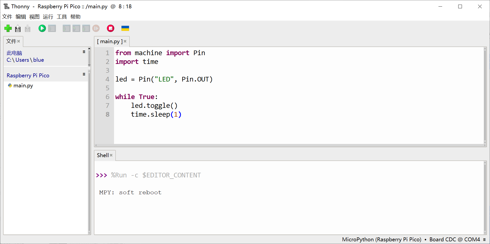
使用 Thonny IDE 可以避免在串口中逐行输入代码。
0x02 功能测试
接下来进行一系列功能测试。
Timer
我们使用以下代码,能让 LED 闪烁:
from machine import Pin
import time

led = Pin("LED", Pin.OUT)

while True:
    led.toggle()
    time.sleep(1)
然而,这份代码是长期占据 cpu 的。可以用 timer 改写:
from machine import Pin, Timer
led = Pin("LED", Pin.OUT)
def blink_func(timer):
led.toggle()
tim = Timer()
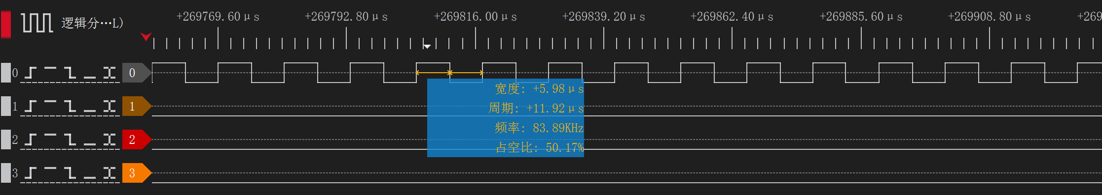
tim.init(period=1000, mode=Timer.PERIODIC, callback=blink_func)现在,我们观察一下 MicroPython 的 GPIO 翻转速度。代码如下:
from machine import Pin, Timer, PWM

pin_out = Pin(6, Pin.OUT)

while True:
    pin_out.toggle()
测试结果,频率为 83.89KHz,翻转间隔为 5.98us,耗时为 c/c++ sdk 直接操作寄存器(8ns)的 747.5 倍。
- 使用 PIO。我们可以在 MicroPython 中配置 PIO 状态机。
- 用 C 语言写一个模块,从 MicroPython 中调用。
I2C
所有的外设都能通过 MicroPython 操作。先来尝试 I2C,扫描总线上的设备:
from machine import I2C

i2c = I2C(0)
print('scan:', i2c.scan())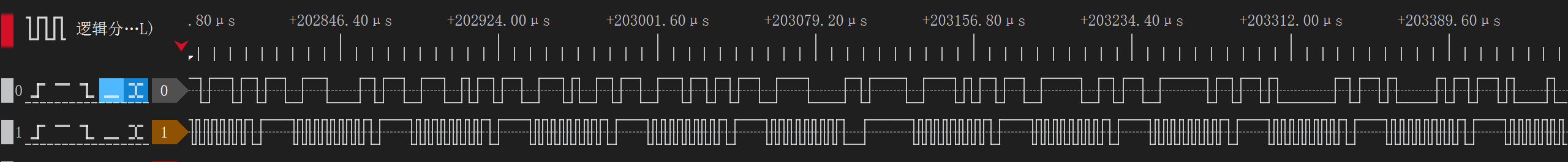
现在用 I2C 连接 OLED 屏幕。本文所用 OLED 屏幕的驱动 ic 是 SSD1306,先安装驱动库:
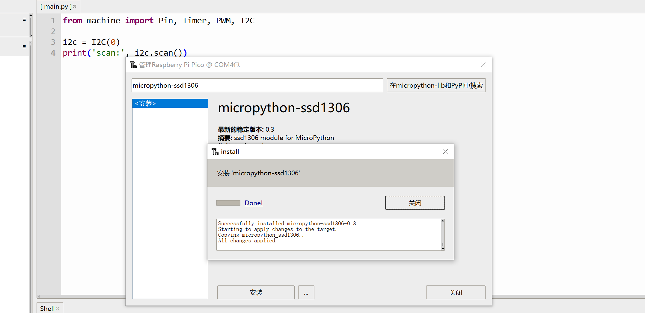
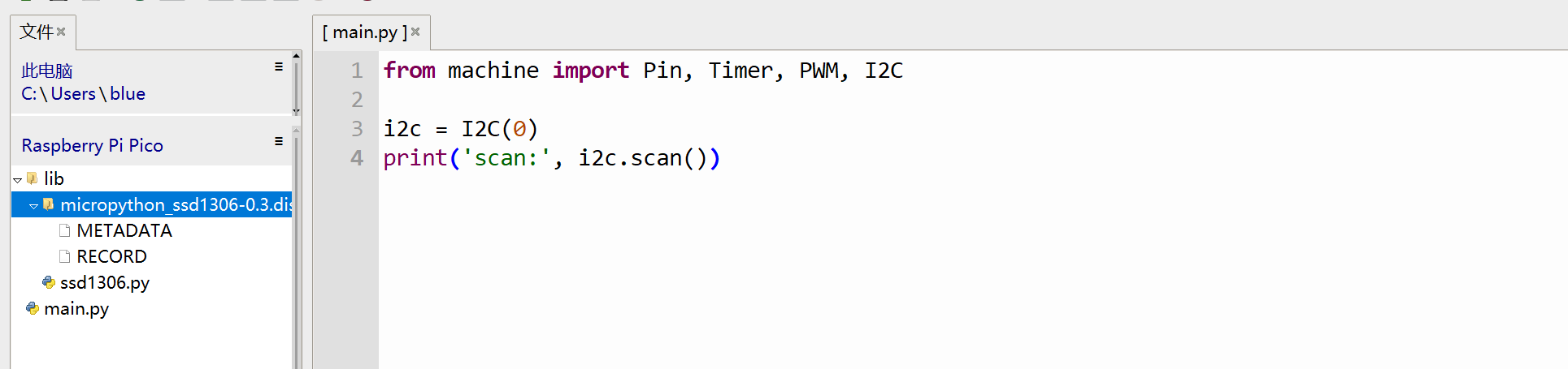
lib 文件夹下出现第三方库使用 pico-micropython-examples 中的代码,展示树莓派 logo:
# Display Image & text on I2C driven ssd1306 OLED display
from machine import Pin, I2C
from ssd1306 import SSD1306_I2C
import framebuf
WIDTH = 128 # oled display width
HEIGHT = 32 # oled display height
i2c = I2C(0) # Init I2C using I2C0 defaults, SCL=Pin(GP9), SDA=Pin(GP8), freq=400000
print("I2C Address : "+hex(i2c.scan()[0]).upper()) # Display device address
print("I2C Configuration: "+str(i2c)) # Display I2C config
oled = SSD1306_I2C(WIDTH, HEIGHT, i2c) # Init oled display
# Raspberry Pi logo as 32x32 bytearray
buffer = bytearray(b"\x00\x00\x00\x00\x00\x00\x00\x00\x00\x00\x00\x00\x00|?\x00\x01\x86@\x80\x01\x01\x80\x80\x01\x11\x88\x80\x01\x05\xa0\x80\x00\x83\xc1\x00\x00C\xe3\x00\x00~\xfc\x00\x00L'\x00\x00\x9c\x11\x00\x00\xbf\xfd\x00\x00\xe1\x87\x00\x01\xc1\x83\x80\x02A\x82@\x02A\x82@\x02\xc1\xc2@\x02\xf6>\xc0\x01\xfc=\x80\x01\x18\x18\x80\x01\x88\x10\x80\x00\x8c!\x00\x00\x87\xf1\x00\x00\x7f\xf6\x00\x008\x1c\x00\x00\x0c \x00\x00\x03\xc0\x00\x00\x00\x00\x00\x00\x00\x00\x00\x00\x00\x00\x00")
# Load the raspberry pi logo into the framebuffer (the image is 32x32)
fb = framebuf.FrameBuffer(buffer, 32, 32, framebuf.MONO_HLSB)
# Clear the oled display in case it has junk on it.
oled.fill(0)
# Blit the image from the framebuffer to the oled display
oled.blit(fb, 96, 0)
# Add some text
oled.text("Raspberry Pi",5,5)
oled.text("Pico",5,15)
# Finally update the oled display so the image & text is displayed
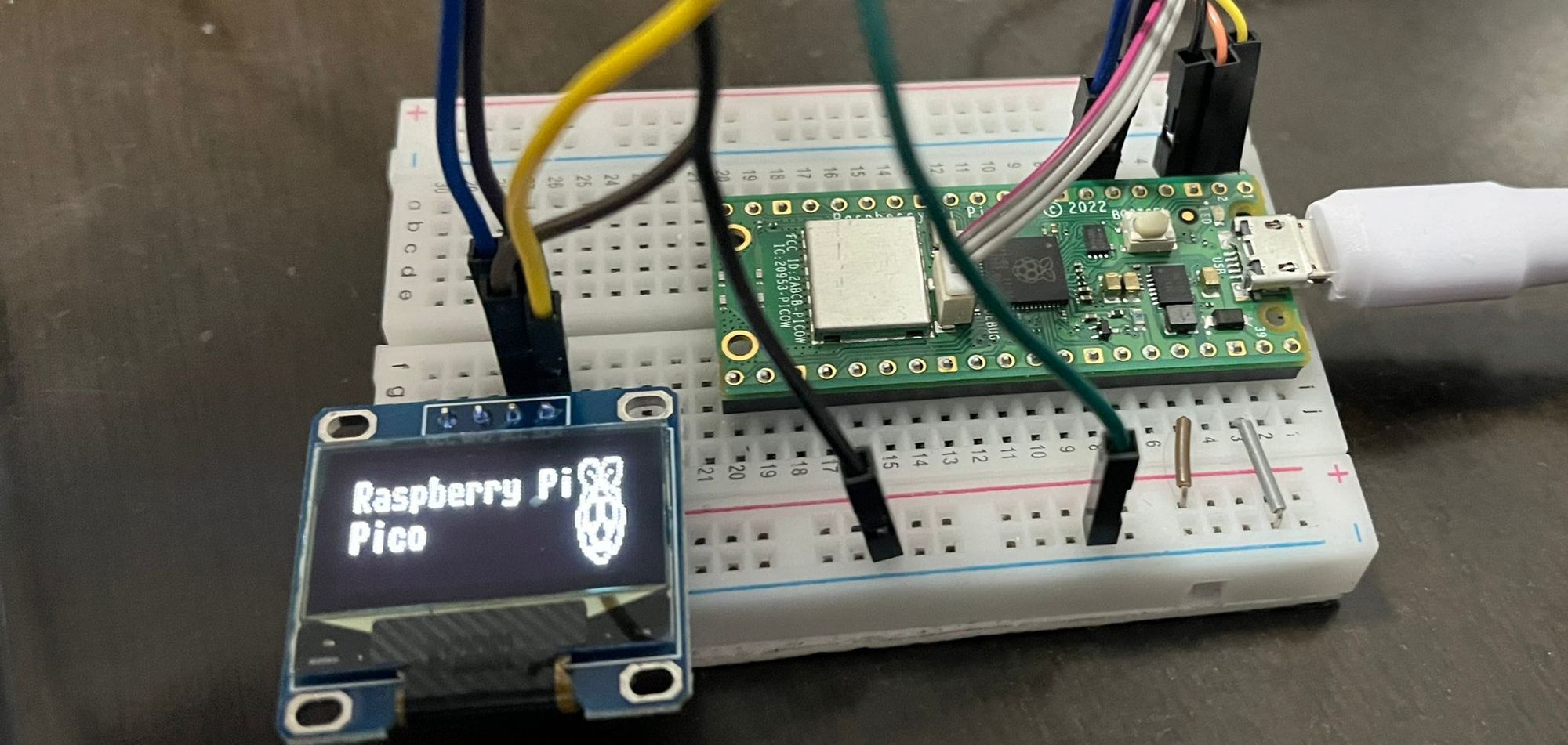
oled.show()
效果:
无线网络
现在来测试 http 功能。代码如下:
import network

wlan = network.WLAN(network.STA_IF)
wlan.active(True)
wlan.connect('<SSID>', '<PASSWORD>')
assert wlan.status() == 3

print(wlan.ifconfig())

import urequests
r = urequests.get("https://www.ruanx.net/robots.txt")
print(r.content)
结果:
>>> %Run -c $EDITOR_CONTENT

MPY: soft reboot
('192.168.10.101', '255.255.255.0', '192.168.10.1', '119.29.29.29')
b'User-agent: *\nSitemap: http://www.ruanx.net/sitemap.xml\nDisallow: /ghost/\nDisallow: /p/\nDisallow: /email/\n'
>>>
可见能正常发起 https 请求。
与 DHT11 通讯
DHT11 采用一种特殊的通讯方式。根据文档,它只有一根数据信号线,MCU 拉低总线 18ms 表示需要获取数据,然后拉高;DHT11 收到请求,将总线拉低 80us 表示应答,然后拉高。接下来,DHT11 发送 40 个 bit,每次发送一个 bit 时,先拉低 50us,然后拉高 26-28us 表示 0,拉高 70us 则表示 1。
上述协议是低速的,可以通过 bit banging 实现。我们无需自己写代码,因为 MicroPython 固件中自带了 DHT11 驱动。代码如下:
import dht
from machine import Pin
sensor = dht.DHT11(Pin(6))

sensor.measure()
print(f'温度:{sensor.temperature()}℃')
print(f'湿度:{sensor.humidity()}%')

# MPY: soft reboot
# 温度:23℃
# 湿度:77%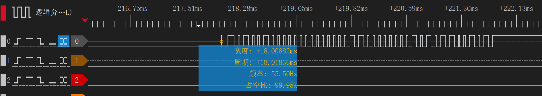
以上,我们测试完了所有与最终任务相关的功能。
0x03 编写联网温湿度计
我们现在开始编写温湿度计的代码。简单梳理一下逻辑:
connect_wifi()

for every 10s:
    get_sensor_data()
    oled_display()
    send_to_server()
最终代码如下:
from machine import Pin, I2C, Timer
from ssd1306 import SSD1306_I2C
import dht
import network
import urequests

def init():
    global sensor, oled, wlan

    sensor = dht.DHT11(Pin(6))
    oled = SSD1306_I2C(128, 64, I2C(0))

    wlan = network.WLAN(network.STA_IF)
    wlan.active(True)
    wlan.connect('<SSID>', '<PASSWORD>')
    assert wlan.status() == 3
    print(wlan.ifconfig())

def get_dht11_data():
    sensor.measure()
    return sensor.temperature(), sensor.humidity()

def oled_display(tem, hum):
    oled.fill(0)
    oled.text("temperature:", 5, 5)
    oled.text(f"{tem} C", 10, 15)

    oled.text("humidity:", 5, 30)
    oled.text(f"{hum} %", 10, 40)
    oled.show()

def send_to_server(tem, hum):
    r = urequests.post(
        "http://192.168.10.102:5000/report",
        json={
            'temperature': f'{tem}',
            'humidity': f'{hum}'
        }
    )

    r.close()

def main_loop(t):
    data = get_dht11_data()
    oled_display(*data)
    send_to_server(*data)

init()
Timer().init(period=10000, mode=Timer.PERIODIC, callback=main_loop)
抓包:
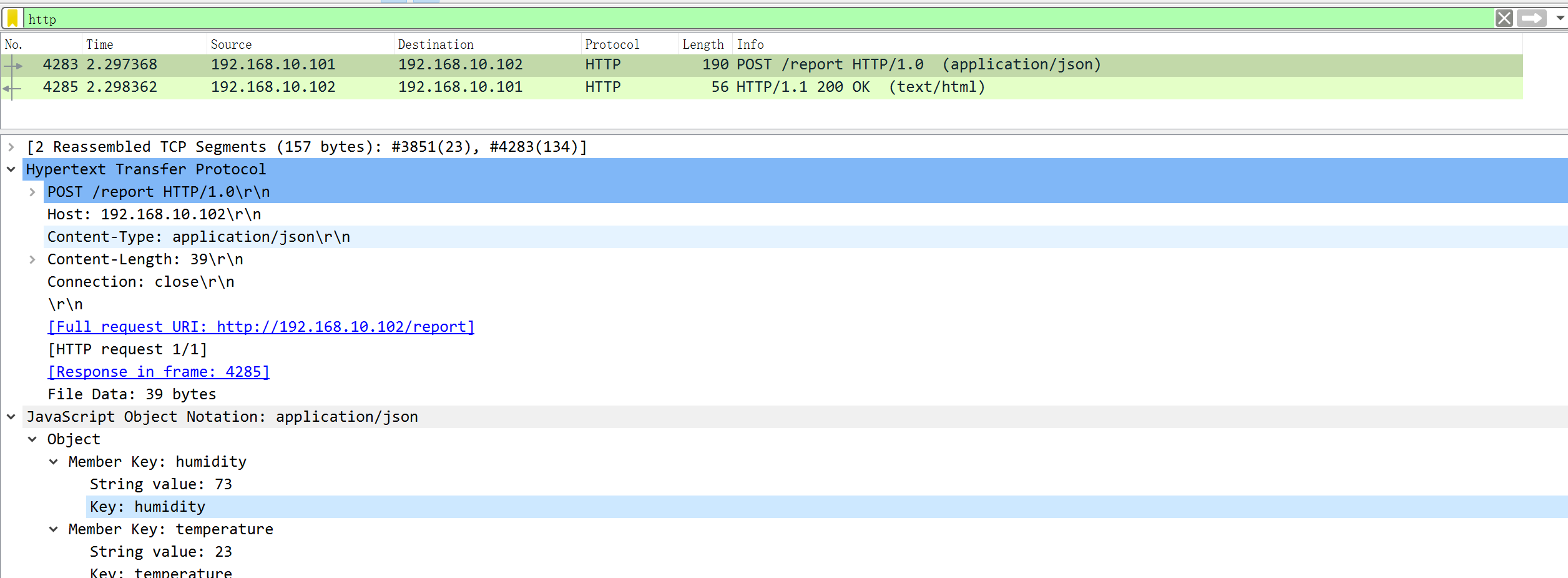
至此,我们通过短短 49 行代码实现了需求。